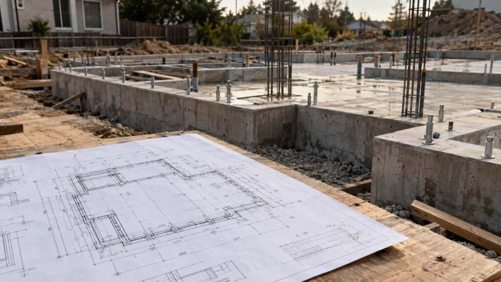
A foundation plan is a scaled structural drawing that shows how a building will be supported at ground level. It identifies elements such as footings, foundation walls, slabs, piers, columns, reinforcement, dimensions, and other details needed to construct the foundation correctly.
For new houses, additions, garages, and other structural projects, the foundation plan commonly forms part of a larger building permit drawing set. It is different from a site plan, which shows where the building sits on the property in relation to lot lines, setbacks, driveways, easements, and surrounding features.
At Get a Site Plan, we prepare non-certified site and plot plans for permit applications. A structural foundation plan can require an architect or engineer depending on the project and your local authority having jurisdiction (AHJ). Always confirm the required drawing set before submitting your permit application.
What Is a Foundation Plan?
A foundation plan is a top-down drawing of the building foundation.
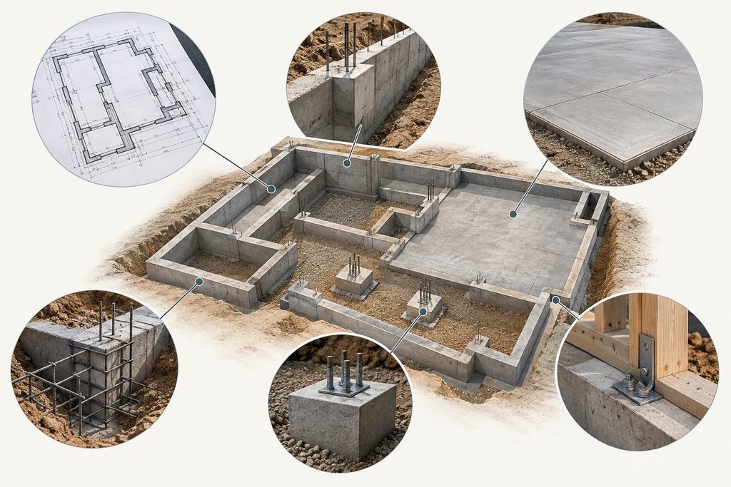
Imagine removing the house and looking directly down at everything supporting it. The drawing identifies where the foundation walls, footings, pads, piers, slabs, and structural supports are positioned.
Its main purpose is to give contractors and building officials enough information to understand how loads from the structure will transfer into the ground.
The 2024 International Residential Code contains detailed requirements for residential foundations and footings, including minimum footing dimensions, soil-bearing considerations, foundation depths, frost protection, and reinforcement requirements in applicable seismic areas. You can review the IRC foundation requirements for the underlying code provisions.
Actual requirements depend on the code adopted by your state or municipality and any local amendments.
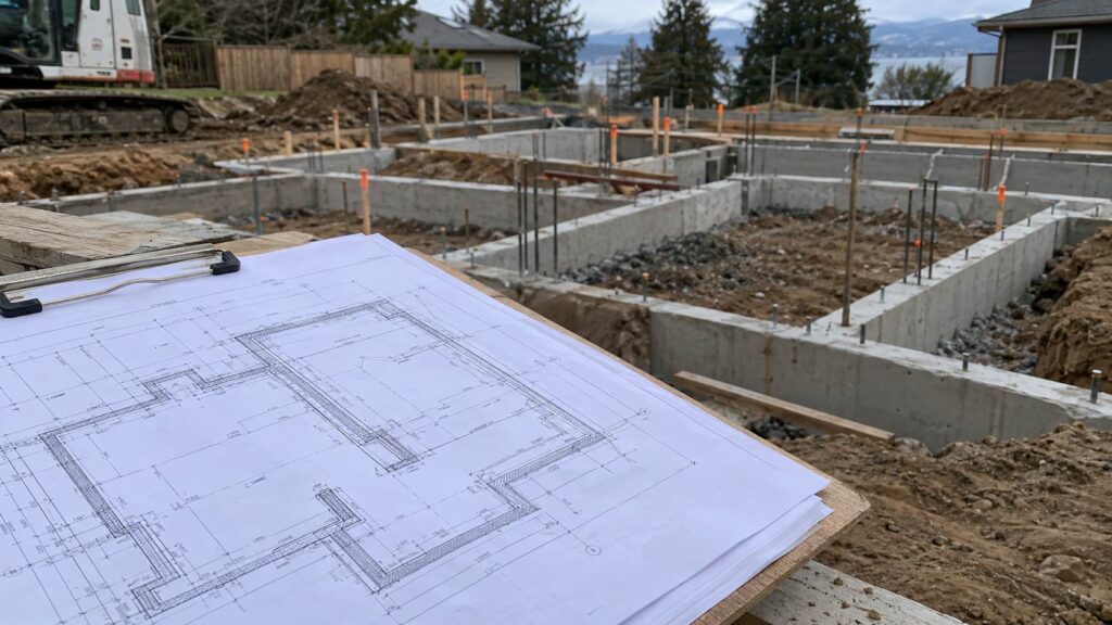
Reinforcement must be properly positioned within concrete to provide the protective cover needed against corrosion.
What Does a Foundation Plan Show?
The exact information varies with the building and foundation type, but most foundation drawings identify several core elements.
Foundation Layout and Dimensions
The drawing establishes the overall foundation footprint.
Dimensions typically identify:
Exterior foundation wall lengths
Interior supporting walls
Footing locations
Pier or column locations
Offsets and changes in foundation shape
Openings and access points
These measurements must coordinate with the architectural and structural drawings above.
Anchor bolts are typically positioned before concrete hardens to ensure proper alignment with the building’s structural framing.
Footings
Footings spread the building load over the soil beneath the structure.
A foundation plan can show continuous strip footings beneath walls, isolated footings below columns and piers, or other engineered footing systems.
Dimensions and notes can identify the footing width, thickness, depth, elevation, and reinforcement.
Bellevue’s structural plan requirements, for example, call for foundation plans to show footing locations, dimensions, elevations, foundation sections, and a footing schedule where applicable. The city provides these details in its structural plan requirements.
Foundation Walls and Stem Walls
Foundation walls carry loads from the building above and transfer them to the footings.
Plans typically identify their:
Location
Thickness
Height
Material
Reinforcement where required
Basement and crawl-space foundations generally require more wall information than a simple slab-on-grade foundation.
Slabs
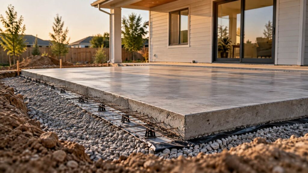
For slab-on-grade construction, the plan can identify slab dimensions, thickness, reinforcement, thickened edges, control joints, and supporting footings.
Local requirements can become quite specific. San Diego’s residential addition guidance, for example, requires applicable foundation drawings to identify footing size, depth, and location, rebar size and spacing, concrete strength, and slab thickness. Those requirements are outlined in the city’s residential addition guidance.
Piers, Pads and Columns
Some buildings transfer concentrated loads through individual columns or posts.
The foundation drawing shows where those loads reach the foundation and identifies the supporting pier or pad footing below them.
This becomes particularly important around beams, porches, decks, large openings, and other areas where loads are concentrated at specific points.
Reinforcement and Connections
Foundation drawings and associated structural details can specify reinforcing steel, anchor bolts, hold-downs, straps, and connections between the foundation and the framing above.
The City of Lincoln’s residential building checklist, for example, calls for footing size, foundation wall size and height, reinforcing steel information, and related foundation details.
Foundation Plan vs. Site Plan
Construction drawings commonly use different scales depending on the level of detail needed, with structural connections often shown at larger scales than overall building layouts.
These drawings answer different questions.
Drawing
Main Question It Answers
Common Information
Foundation plan
How is the building supported?
Footings, slabs, foundation walls, piers, reinforcement
Heights, rooflines, doors, windows, exterior materials
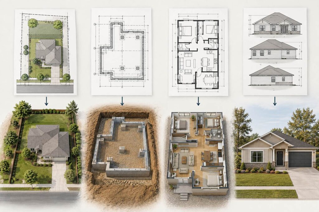
For a new building, you can need all four.
A construction permit site plan places the proposed building footprint on the parcel and establishes its relationship to property lines and surrounding site features.
The foundation plan then provides the construction information for the structure below that footprint.
The floor plan documents the layout above the foundation, while elevation drawings show the exterior from one or more sides.
Three Common Foundation Plan Examples
Foundation drawings change significantly depending on the system supporting the building.
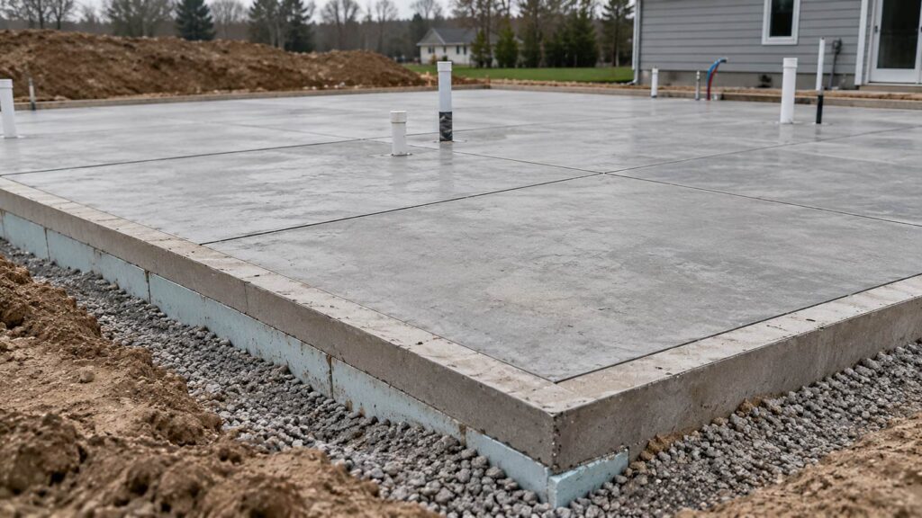
1. Slab-on-Grade Foundation Plan
Control joints create planned weak points in concrete, helping cracks form in less noticeable locations as the slab shrinks during curing.
A slab-on-grade foundation places the concrete slab close to finished ground level.
The plan can show:
Slab perimeter
Continuous or thickened-edge footings
Interior thickened sections
Reinforcement
Column pads
Anchor locations
Construction joints
This system is common where soil, climate, building design, and local code make a slab foundation appropriate.
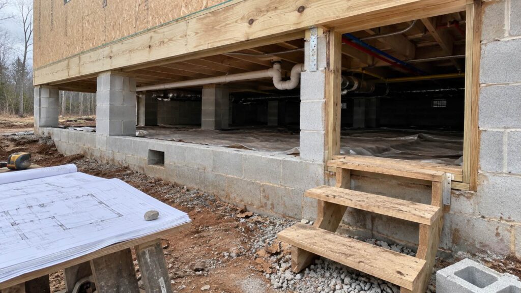
2. Crawl-Space Foundation Plan
Crawl-space access openings must be large enough for inspection and maintenance, with minimum dimensions specified by local building codes.
Its foundation plan usually contains continuous perimeter footings and foundation walls together with interior piers or supporting walls.
Crawl-space access and ventilation can also appear on the plan. Portland specifically requires foundation plans for applicable residential projects to show continuous slabs, footings, reinforcing steel, concrete information, crawl-space access, and foundation vents. Its permit plan guide explains the required drawing information.
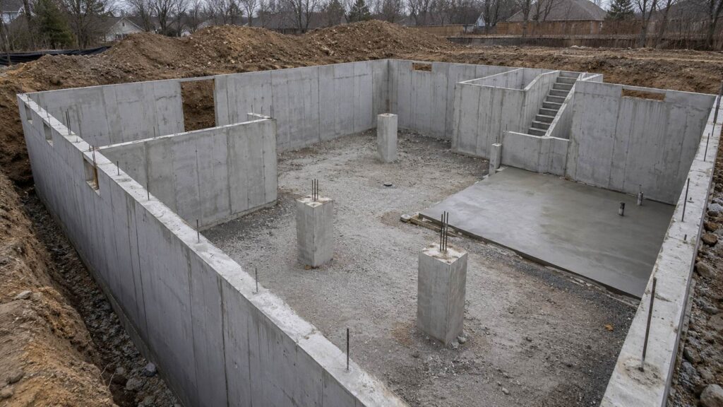
3. Basement Foundation Plan
Basement walls often require temporary bracing during construction until the floor framing provides permanent lateral support.
A basement foundation extends farther below grade and uses foundation walls to form the basement perimeter.
Plans can show:
Basement walls
Continuous footings
Interior columns
Pad footings
Beam support locations
Foundation steps
Openings
Slab areas
Reinforcement
Additional sections and details normally accompany the plan because wall height, soil pressure, drainage, waterproofing, and structural loads become important considerations.
What Does a Foundation Plan Look Like?
At first glance, a foundation plan resembles a simplified floor plan with many structural notes.
Heavy lines can represent concrete walls or footings. Dimension strings establish distances between structural elements. Symbols identify piers, columns, section cuts, reinforcement, or special details.
Labels might reference another drawing, such as:
SECTION A/A – SEE S3.1
That tells the reader to look at another sheet for a vertical section showing how the footing, wall, reinforcement, slab, framing, and surrounding grade connect.
A good foundation drawing should therefore be read together with its sections, schedules, notes, and structural details.
Do You Need a Foundation Plan for a Permit?
Building inspectors may check footing dimensions and reinforcement placement before concrete is poured, making this an important inspection stage.
For new construction and substantial structural additions, frequently yes.
The City of Alameda lists a foundation plan among its structural plan requirements for new residential construction and applicable additions.
It also identifies plot plans, floor plans, exterior elevations, structural details, calculations, and soils information among documents that can be required depending on the project. The city’s residential permit requirements provide an example of how extensive a permit drawing set can become.
That does not mean every small residential project needs a full structural foundation plan.
Requirements depend on:
Project type
Foundation system
Building size
Local building code
Soil conditions
Flood or seismic conditions
Local amendments
Whether prescriptive construction is allowed
Check with the AHJ before preparing the permit set.
Some do. Others can follow prescriptive residential code provisions.
The deciding factors include the structure, loads, soil conditions, foundation design, local code, and permitting authority.
Engineered foundations become more likely when a project involves unusual soil conditions, significant retaining loads, complex structural loads, large buildings, steep sites, certain seismic conditions, or a foundation outside prescriptive code provisions.
A clean CAD drawing alone does not make a foundation structurally engineered. Structural design, calculations, and professional certification are separate issues.
How the Foundation Plan Fits Into Your Permit Se
A building department reviews the project as a coordinated set of drawings rather than as several unrelated pages.
The site plan establishes where construction occurs.
The foundation plan establishes how the structure meets the ground.
The floor and framing plans establish how the building above is arranged and supported.
Elevations and sections establish height, exterior configuration, and vertical construction details.
If your building department requires a site or plot plan alongside the structural drawings, Get a Site Plan can prepare a professional, scaled, non-certified site plan for permits using available GIS data, satellite imagery, public property information, and documents or dimensions you provide.
We prepare plans remotely, so no site visit is normally required. Our drawings do not replace a legal survey, architect, or structural engineer when your AHJ specifically requires one.
FAQs
No. A foundation plan shows the structure supporting the building. A floor plan shows rooms, walls, doors, windows, and other features at a particular floor level.
No. A site plan shows the building’s location on the property. A foundation plan shows how the building itself is supported.
Yes. Footing locations, sizes, dimensions, and related details are core parts of many foundation plans.
Foundation drawings can show rebar, reinforcing schedules, anchor bolts, hold-downs, and related structural information when required.
They are commonly required when an addition includes new structural foundations. Your local building department determines the exact submittal requirements.
The foundation plan is normally read together with structural sections, details, specifications, calculations, and the rest of the approved construction set.
No. Our non-certified drawings do not replace engineering, architectural, surveying, or other licensed professional services when those services are required.
Ask your building department for its current permit checklist. Confirm whether it requires a site plan, foundation plan, engineered structural drawings, survey, floor plans, elevations, or additional documentation before you submit.
Learn more about our contributor:
Jennifer Booker
Contributing Writer | Architecture & Design Writer
During my career, I’ve written articles on interior design, home remodeling, and renovation with an emphasis on money-saving tips and DIY ideas. It’s been a rewarding journey and I am thrilled to continue helping others bring their architectural visions to life.
Building a driveway starts well before the first load of gravel or concrete arrives. You need to choose the location and material, check drainage, identify underground utilities, prepare a stable
For most new homes, a slab foundation costs less and requires less maintenance. A crawl space costs more upfront, yet provides easier access to plumbing, electrical lines, HVAC components, and
The best site plan software for 2026 includes AutoCAD, SmartDraw, Cedreo, SketchUp, ConceptDraw, ArcSite, ZWCAD, RoomSketcher, and LibreCAD. Each serves a different purpose, from simple backyard layouts to detailed construction