
How Much Does It Cost to Build a Shed – Full Breakdown 2025
Imagine having a place that’s only a few steps away from your back door, that can be dedicated to your creative space. Building a shed can be a great addition
This is Not a Legal Survey


Contributing Writer | Architecture & Design Writer
Architectural drawings are the backbone of construction projects, including new construction, renovations and various projects. Explore their types, roles in the construction and permitting process, and how CAD software can help you transform plans into actionable construction steps.
Table of Contents
ToggleAn architectural drawing includes sketches, plans, diagrams, and schematic illustrations that convey comprehensive details about a building. These technical illustrations are made by architects and designers in the initial stages of a construction project.
Architectural drawings are made to systematically translate a design concept into a series of coherent steps within working drawings. Together with other categories of engineering drawings, they come together in a cohesive framework of design. Architects then directly present these sets of drawings to clients and local government regulatory bodies.
There are 9 main types of architectural drawings, let’s explain them.
The site plan is an architectural drawing that shows the lot, its surroundings, and every structure located on it. The site plan shows the boundaries of your property and nearby structures if they are in any way relevant to your project.
Site plans are very important because they show the exact distance between structures on your lot and the existing and proposed buildings. This is crucial for getting any type of building permit. So, having a site plan for permits is one of the most important architectural drawings in any construction process.
The floor plan is a technical scale drawing that illustrates the layout of a building from above. The floor plan serves as an internal illustration of the structure, capturing intricate design components like electrical or plumbing systems, as well as precise measurements detailing the distances between walls, doors, and windows within the building.
Floor plan drawings are very important during the design process. Having a custom floor plan can help you arrange your furniture, decide on the perfect flow in your space and build a home according to construction codes and building regulations.
(Click on the image on the right to enlarge and see the details on the floor plan drawing.)
An architectural elevation drawing is designed from a vertical perspective, providing a direct view of the building. In this case, the vertical perspective is depicted from a frontal viewpoint, capturing the building’s exterior as seen from its front, back, and sides.
Cross-section drawings depict the structure as it was sliced vertically, so you can see the hidden and visible elements of the building. It is a two-dimensional architectural drawing.
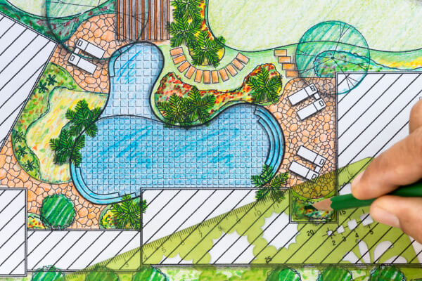
Landscape architectural drawings are very similar to site plans, but they are not focused on buildings but on the landscape. These drawings are very useful in residential construction projects for creating a perfect landscape design.
An excavation drawing illustrates the measurements of a building’s foundation, aiding in establishing the necessary depth of excavation and the dimensions required for the foundation. These drawings are crucial in guiding construction teams.
The great benefit of excavation drawings is that your construction team will know what materials need to be removed, what methods to use, and what specific tools they need to have to accomplish the excavation process.
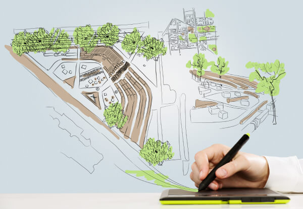
Detail architect drawings offer a magnified perspective of a specific portion of the construction. This will enable you a closer examination of how individual components of your project interconnect.
This combination of many close-up views can really help you in the design process because you are able to see each decorative element. Also, detailed drawings can serve during the construction process because they can show how reinforced concrete beams are assembled.
An as-built drawing is a visual representation that contrasts the present condition of a newly constructed building with its initial plans or blueprints. This form of illustration proves invaluable in situations where unexpected factors surface, compelling architects to modify their plans.
Furthermore, an as-built drawing serves construction teams by aiding in progress tracking and identifying pending tasks. Architects typically generate these drawings upon the project’s completion.
Architectural location drawings (also called general arrangement drawings) are a general category that includes all drawings that show the composition of your project. If there is any future work related to the project, it will be shown on the location drawings.
Let’s take a look at some examples of architectural drawings.


There are two main drawing styles in architecture:
The main difference is that architectural sketches and diagrams are done by hand, while CAD drawings are made using computer software.
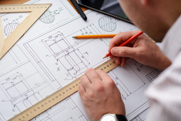
A sketch represents a swiftly executed freehand drawing. This is a rapid method to capture and evolve an idea, without aiming for a polished outcome. An architectural diagram can also be produced freehand, but it needs symbols to develop the logical structure of a design. Both sketches and diagrams can be refined into a more polished form.
Because the entire process of designing can become long, these forms of drawings are essential for architects. Designers of various specialized disciplines, including architects, initiate the exploration of a new concept through sketches and diagrams.
After the design has been confirmed, they go to more advanced drawings which are CAD drawings made with architectural drawing software.
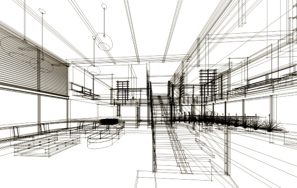
CAD drawings are 2D or 3D computer-generated detailed illustrations of an architectural project. CAD drawings encompass a computer-rendered depiction of the design, showing its dimensions, textures, and materials.
These drawings come in either two-dimensional or three-dimensional formats. The process of creating a 3D object using CAD is often termed “rendering” or “modeling,” while 2D design is commonly referred to as “drafting.”
Architects utilize architectural drawings as a pivotal tool to transform design concepts into well-structured design proposals. These technical drawings serve as a means of effectively communicating ideas and concepts. They capture the overall aesthetic of both interior and exterior aspects of a building and offer precise measurements.
There are 2 very important stages that need architectural drawings:
So, let’s explain them.
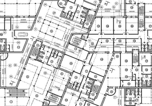
Every construction project requires well-defined and complex architectural and construction drawings for its realization. In the building construction process, the guidelines provided by comprehensive architectural designs are of utmost importance for contractors to carry out their work. These drawings include elevation and section views, which serve as a blueprint for the construction crew.
During the construction phase, every contractor will adhere to the architectural drawings because this is the only way that guarantees a process that is safe, compliant with regulations, and aligned with the design and preferences of clients. Also, these construction blueprints will eliminate any unwanted surprises during construction.
Local authorities and inspections request obtaining permits before any construction project. Some of the necessary documents are architectural drawings. These technical drawings are prerequisites for project approval, as they ensure compliance with local building and zoning codes.
Some of the standard scales for different types of architectural and construction drawings are:
As you can see, the more detailed drawings with different construction elements have a larger scale. If we are talking about very intricate, small, and detailed elements, they can even be full-size (1:1 scale).
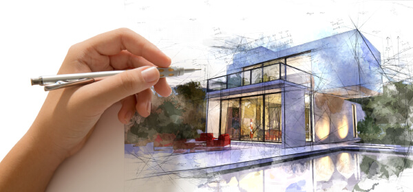
Perspective in architectural drawing is a representation of what we perceive with our eyes on the flat surface of a drawing. The fundamental principles include:
Artificial perspective can be categorized based on the number of vanishing points:
In architectural perspective, the practice is using a two-point perspective, maintaining verticals as true vertical lines on the drawing.
Creating a comprehensive set of architectural drawings involves several key steps, which serve as the foundational blueprints for future construction endeavors, including electrical, plumbing, engineering, and mechanical aspects. Those steps are:
But what if you aren’t an architect and you need some professionally made architectural drawings? No worries, we got you covered.
If you are not able to create different construction drawings using CAD software, that is perfectly fine. There is a quicker and easier way. If you check our services you will find the architectural drawing you need, order it and our expert drafters will deliver it to you in 24h or less.
Learn more about our contributor:

Contributing Writer | Architecture & Design Writer
During my career, I’ve written articles on interior design, home remodeling, and renovation with an emphasis on money-saving tips and DIY ideas. It’s been a rewarding journey and I am thrilled to continue helping others bring their architectural visions to life.

Imagine having a place that’s only a few steps away from your back door, that can be dedicated to your creative space. Building a shed can be a great addition

Building a deck is a great way to transform your outdoor space into a more appealing and functional area for relaxation and entertainment. To ensure the deck’s safety and durability,

Are you looking to modernize your pool with an outdated design and want to improve its functionality? If so, you’re in the right place. Imagine transforming your basic swimming pool