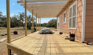
Deck Building Cost – Average Prices + Saving Tips [2026 Data]
Building a new deck costs $8,321 on average in 2026, with most homeowners spending between $4,339 and $12,653. According to Angi’s 2026 deck cost data, those figures come from more




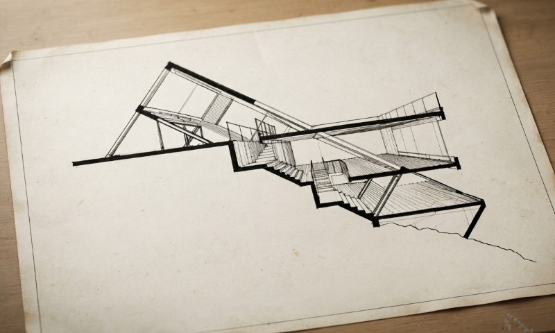

Architectural section drawings show a building as if it were cut vertically and opened up for inspection. They reveal information that floor plans and exterior elevations cannot show clearly, including floor-to-floor heights, roof construction, foundations, wall assemblies, stairs, ceiling levels, and the relationship between different parts of a structure.
A section is one part of a complete drawing set. A floor plan shows the building from above, while an elevation drawing shows one exterior side. A section cuts through the building and exposes what is happening inside.
For permit work, the exact drawings required depend on the local authority having jurisdiction. Get a Site Plan provides online drafting services including non-certified site plans, floor plans, elevations, and custom drafting.
Our drawings do not replace a licensed architect, engineer, or surveyor when a stamp, structural design, certification, or professional analysis is required. We do not issue permits, and the local building department decides what it will accept.
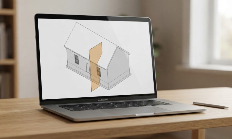
An architectural section is a two-dimensional vertical view through a building, structure, or specific construction element.
Imagine cutting straight through a house from the roof to the foundation and removing the portion closest to you. Everything exposed by the cut becomes part of the section drawing.
A typical section can show:
Portland’s building department describes a residential section as a vertical cut extending from the roof through the ground. Its permit plan guidance also uses sections to communicate structural conditions and construction materials during plan review.
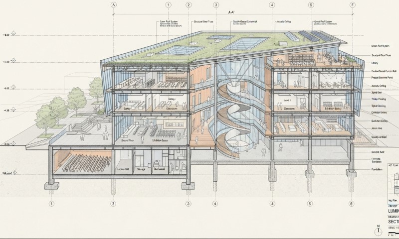
Plans, elevations, and sections describe the same building from different viewpoints.
| Drawing | View | Main Purpose |
| Floor plan | Horizontal view from above | Shows room layout, walls, openings, and dimensions |
| Elevation | Vertical exterior view | Shows the appearance and height of one side |
| Section | Vertical cut through building | Shows internal heights, assemblies, structure, and levels |
| Detail | Enlarged view of one area | Shows a specific connection or construction condition |
A good drawing set uses the views together.
For example, a floor plan can show where a staircase begins. An elevation can show windows beside it. A section explains the stair rise, floor levels, ceiling clearance, and connection between stories.
Our guide to the main types of architectural drawings explains how the major drawings in a set communicate different parts of a project.
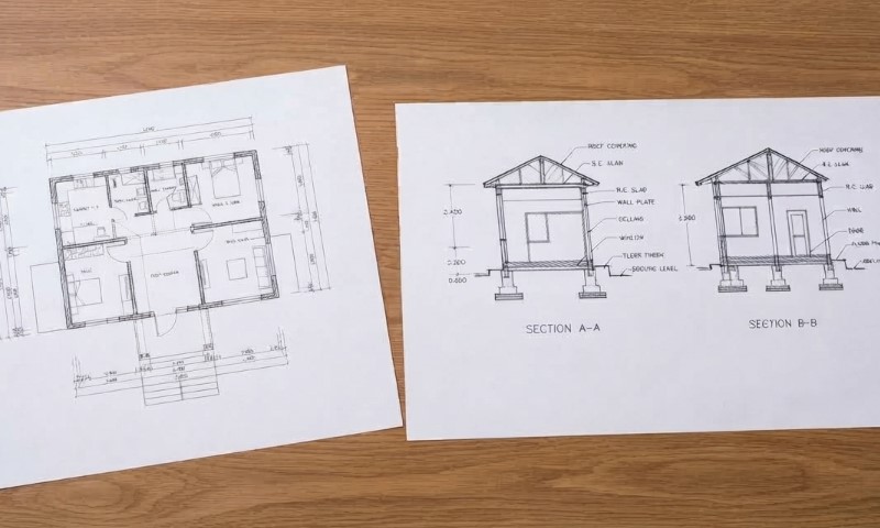
Several section types are used in residential and commercial drawing sets. Their names describe either the direction of the cut or the amount of construction shown.
A building section cuts through a large portion of the structure, usually from one exterior wall to the other.
It gives the reader an overall view of vertical relationships within the building.
A residential building section can show the foundation, first floor, upper floor, attic, roof, stairs, and grade on one drawing. Dimensions commonly identify floor-to-floor heights, ceiling heights, roof elevations, and foundation depth.
Building sections are especially useful for multi-story homes, additions, split-level designs, vaulted spaces, and projects where roof and floor heights must be coordinated.

A longitudinal section runs along the longer dimension of a building.
On a rectangular house, the cutting plane usually follows the building length. The resulting view can expose several rooms, structural bays, roof changes, and floor levels within one image.
Longitudinal sections work well for narrow buildings, sloped sites, long additions, and structures with major changes in elevation from one end to the other.
A transverse section cuts across the shorter dimension.
For a conventional house, a transverse section can provide a clear view of the roof shape, floor system, exterior walls, foundation, and overall building width.
Architects and drafters select longitudinal and transverse cuts according to the information that needs to be communicated. A complex project can use both.
A wall section focuses on a narrow vertical strip through an exterior or interior wall.
The drawing uses a larger scale than a full building section, allowing individual construction layers to appear clearly.
A wall section can identify:
Wall sections become important when reviewers and contractors need construction information that cannot fit clearly on a general building section.
A detail section enlarges one specific condition.
Common examples include a roof eave, window head, foundation connection, parapet, stair connection, balcony edge, deck attachment, or wall-to-roof junction.
A detail section does not need to show the entire building. Its purpose is to explain one construction condition with enough scale to identify materials, dimensions, fasteners, flashing, clearances, or other technical information.
A partial section cuts through only part of the building.
A drafter can use one to explain a porch, stair, basement, foundation transition, roof intersection, or other limited area without creating another full building section.
The National CAD Standard recognizes sections as a distinct drawing category and separates general sections from larger-scale views and details.
A section starts with a cutting plane.
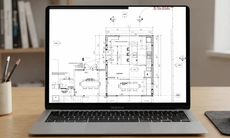
On the floor plan, a section line shows where the imaginary cut passes through the building. Arrows or section symbols indicate the direction the viewer is looking.
The marker normally refers to the section number and the sheet where the section appears.
For example, a marker could direct the reader to Section 2 on architectural sheet A-301. The reader can locate the cut on the floor plan, follow its direction, and then find the corresponding section drawing.
Standardized section indicators make larger drawing sets easier to navigate. Section indicator conventions published through the National CAD Standard show examples for full-building and partial-building sections.
The amount of information depends on the project and review requirements. A basic residential section generally needs enough detail to explain the building vertically.
| Element | Information Commonly Shown |
| Foundation | Footings, foundation walls, slab, crawl space, basement |
| Floors | Finished levels, joists, slabs, floor thickness |
| Walls | Heights, framing, materials, openings |
| Roof | Pitch, ridge, rafters or trusses, overhangs |
| Stairs | Rise, run, landings, headroom |
| Openings | Window and door heights |
| Grade | Existing or proposed ground relationship |
| Dimensions | Vertical heights and critical distances |
Structural projects require more information. The 2024 International Residential Code states that permit construction documents must have enough clarity to describe the location, nature, and extent of proposed work.
It also allows the building official to require documents prepared by a registered design professional when necessary. The relevant requirements appear in the IRC administration provisions.
Local requirements control the final drawing set.
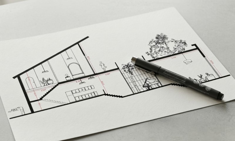
The easiest way to understand sections is to consider common residential projects.
A section through a rear addition can show how the new floor meets the existing floor, how the roof connects to the existing house, and how the new foundation reaches the required depth.
The corresponding site plan drawing shows where the addition sits on the property. The floor plan shows its internal layout. The section explains its vertical construction.
A full section through a two-story home can show the foundation, first-floor ceiling height, second-floor structure, upper ceiling, attic, and roof.
The drawing gives reviewers a quick way to verify the overall vertical arrangement.
A transverse section through a gable roof can show roof pitch, ridge height, ceiling configuration, insulation space, and eave conditions.
An exterior elevation complements the section by showing the roof and façade from outside.
A stair section can show risers, treads, landings, headroom, floor levels, guards, and handrails.
A floor plan alone cannot communicate all of those vertical relationships clearly.
A foundation section focuses on the connection between the building and the ground.
It can show footing dimensions, foundation walls, slab elevation, crawl space clearance, waterproofing, drainage, and surrounding grade where required.
Structural sizing and engineering calculations belong to a qualified design professional when local regulations or project conditions require them.
Section drawings are required for many new buildings, additions, major alterations, and projects involving structural changes.
They are not required for every permit.
Requirements vary by jurisdiction, which is why checking the local submittal checklist before preparing a drawing set is important. Our building permit guide explains the basic permit process and how construction documents fit into an application.
When the building department requires stamped architectural or structural documents, a non-certified drafting service cannot replace them.
Get a Site Plan prepares professional non-certified drawings for homeowners, contractors, property managers, and other clients who do not need a professional stamp.
Our services include site plans, floor plans, elevations, 3D renderings, and custom drafting work for projects with specific requirements.
For a typical project, send us the property information, available measurements, sketches, surveys, existing plans, or other reference material. Our team can determine which of our drafting services fits the information you need documented.
Contact the local building department first when architectural sections, structural details, engineering calculations, or sealed construction documents appear on its permit checklist.
The authority having jurisdiction has the final say on the drawings and professional credentials required for approval.
A section drawing is a vertical cut through a building that shows internal construction, floor levels, roof conditions, foundations, and other features hidden from exterior views.
An elevation shows a building from the outside. A section cuts through the building and shows internal conditions.
A building section is a large vertical cut through a significant portion of a structure, usually extending from the foundation to the roof.
A wall section is a larger-scale vertical drawing focused on the materials and construction layers within a wall, roof, floor, and foundation connection.
A section line marks the location of the cut on a plan. Its symbols indicate the viewing direction and reference the corresponding section drawing.
Many new construction, addition, and structural alteration permits require them. Requirements depend on the local building department.
No. A floor plan communicates the horizontal layout, while a section communicates vertical construction and relationships.
A stamp is required when state law, local regulations, project scope, or the building official requires documents prepared by a licensed professional.

Building a new deck costs $8,321 on average in 2026, with most homeowners spending between $4,339 and $12,653. According to Angi’s 2026 deck cost data, those figures come from more

A general contractor manages the construction side of a project from pre-construction through completion. The job usually includes coordinating subcontractors, ordering materials, managing schedules, handling inspections and permits when required
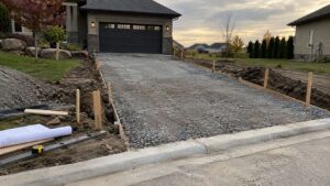
Building a driveway starts well before the first load of gravel or concrete arrives. You need to choose the location and material, check drainage, identify underground utilities, prepare a stable
